Passengers at the new Farringdon Crossrail station will be greeted by a sequence of stunning concrete ceilings, writes Tony Whitehead
In March, Farringdon became the first Crossrail station to be handed over to Transport for London. It is notable for a number of reasons, not least its BREEAM Excellent environmental rating. But for passengers departing from this fashionable quarter of the capital, the first thing that will strike them is a stunning cathedral-like concrete ceiling. In fact, this is the first of three such spaces, each a showcase of what different types of concrete construction can achieve.
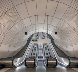
The station has two entrances, some 400m apart, and as you enter the westernmost of these, at Cowcross Street, the first of the spectacular ceilings is soon visible. Known as the upper apse, it comprises a lattice of concrete beams arranged in a diamond pattern. These support the sloping concrete panel soffit of a wide stairway with escalators leading down to the station’s intermediate level. The beams are massive – up to 12m long. Yet they are also smooth and elegant.
Crossrail says that the diamonds reflect the fact that this entrance is adjacent to the gem-dealing quarter of Hatton Garden – and indeed the X-shaped concrete nodes at the beam intersections even feature cast-in spaces for powerful downlights that shine like enormous solitaires. But the design also has a subtler genesis. “The design evolved under the influence of many factors,” says Soji Abass, Crossrail’s lead architect for the station.
“For example, we wanted to avoid metal ceilings, which require ongoing maintenance. Metal panels get opened and closed to access hidden services and begin to look tired after a while, and there are safety issues with working at height. In contrast, these concrete ceilings are low maintenance.”
Hatton Garden certainly influenced the diamond shape, he adds. But the angle at which the beams are set is also taken from the meeting of the two railway lines at this point. “Once we had the angle, the diamonds naturally followed, and we’ve then taken advantage of the column-free space to exploit the perspective offered by the sloping soffit.
The idea is that the pattern acts as a sign or wayfinder, so people intuitively know where to find the route to the platform. But above all, we just wanted a delightful way for passengers to get from the street to the lower level.” This use of perspective is very effective, though passengers will have little clue how difficult the 25m-wide ceiling was to build. The whole 360-tonne ceiling is suspended from an invisible steel structure above – so the overriding challenge for the contractor was how to safely construct such a ceiling, high above a sloping stair ramp, and beneath the structure that would support it.
A number of potential solutions were examined, as Duarte Seixas, project manager with BFK (the Bam, Ferrovial, Kier joint venture that built the station) explains: “We looked at making this ceiling from in-situ concrete, but it would have been very hard to achieve the finish we wanted on an incline. It would also have been difficult to crane material and reinforcement through a heavy steel structure above. We looked at making just the beams from in-situ and putting precast panels above, but dismissed this for the same reason, so in the end we agreed that the whole ceiling should be precast.”
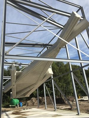
There remained, however, the problem of how to thread 102 large concrete elements through the supporting structure above the ceiling. “It was not doable,” says Seixas, “so the solution was to construct a large, inclined, temporary steel structure on which the concrete ceiling could be assembled. The permanent steel structure was built on top, connected to the concrete, and then the temporary steel structure below was removed.”
To check that this would work, a large mock-up – with steel supports and an entire diamond’s worth of beams and panels – was constructed at the factory of the precast supplier, Evans Concrete Products in Alfreton, Derbyshire. “This helped us get a lot of answers,” says Seixas. “We tested the finish, the joints, the cast-in recesses for the lights, and even how to lift the sections. Remember, we had to lower these large elements onto an inclined structure, so the lifting eyes had to be oriented to accommodate the angle and positioned to ensure the weight would be balanced.”
Once the beams and nodes had been assembled on the temporary structure, the diamonds were then “filled in” with 63 precast slabs placed on ledges running along the sides of the beams. Interestingly, these slabs are not fixed to the beams, but lie loose on the ledges. The reason for this is that, in the event of a bomb blast, the force of the explosion will briefly lift the panels from the beams. This will allow the blast pressure to escape into the voids above, and so prevent the force of any explosion remaining concentrated in the highly populated areas below.
“Mitigating the effects of bomb blast is something that affected quite a bit of the design,” says Seixas. “To minimise flying debris, for example, cladding panels needed firm fixing to a resilient substrate. Concrete or blockwork walls offered the structural robustness we needed for this.”
With the ceiling fully assembled, the permanent steel structure could be constructed above, and fixed to the ceiling via large steel connecting plates cast into the beams. Then came the nerve-racking process of removing the temporary steelwork below. “We checked and triplechecked everything before doing this,” says Seixas. “We carried out a finite element analysis to determine how the ceiling was going to behave – how it would deflect – once the supporting structure was removed.
 Once the escalator shaft from the western ticket hall had been excavated, the contractor needed to backfill part of it to create a solid 30° ramp for the escalator to sit on. The default way of doing this would have been simply to fill the void with in-situ concrete, but the construction team came up with a more ingenious plan.
“We realised we already had concrete we could use to fill this space,” says Duarte Seixas, project manager with contractor Team BFK. “Another shaft on the site has a secant-piled concrete wall holding back the earth. But as construction progressed, it was always planned that some of these piles would have the tops sliced off to allow for the construction of floor slabs and other features.
We looked at using this waste concrete as the backfill, and decided it could work.” The decision involved analysing how strong an assemblage of pile tops would be, and working out how to orient them to fill the void in a way that was both stable and efficient. “In all we had some 40 pile tops, most of them about 2.5m long and weighing around six tonnes each. Some larger 4m sections were cut in half, so we were dealing with more consistent, manageable weights.”
As they were removed, these cylinders of reinforced concrete were stacked horizontally, like a pile of logs, to create the backfill. “We would arrange up to three pile sections in a line to fill the space, then another three adjacent to them and so on. Once we had a whole layer, we would stabilise it by filling in the gaps with poured concrete – but considerably less than if we weren’t using the pile tops. Once one layer had cured, we could arrange another layer of piles on top, until we had built up the entire incline for the escalator.”
As Seixas explains, the technique achieved more than just reducing the need for new concrete: “If we hadn’t reused this concrete, we would have had to crush it and remove it from the site. So reusing it reduced noise, dust and site traffic, and helped our programme too.” The contractor calculated that reusing the pile tops saved a total of 16 waste collections, 23 concrete deliveries and 170m3 of concrete – in all, amounting to 25 tonnes of CO2.
If we got it wrong, the ceiling could crack, so we worked out a sequence of releasing the support in phases so that at no stage of its removal would any part become too stressed. After each area of support was removed, the deflection was checked before moving onto the next one.” The result is worth the effort – the intersecting beams creating a bold pattern which, Abass says, changes depending on where you view it from. Ironically, while the concrete appears to express the structure, it is not itself structural, being suspended from the nowinvisible steelwork above.
By comparison, the ceiling of the area at the bottom of the escalators, known as lower apse, was simpler to make, though still unusual in its construction. This comprises 225 flat diamond shaped precast panels, each set slightly proud of an in-situ concrete slab. This ceiling supports itself, so there was no issue this time with steelwork above. Nevertheless, various methodologies for its construction were discussed. “Again we considered doing this with insitu,” says Seixas, “but thought we would struggle to match the finish of the precast upper apse ceiling.
Having them both precast helps them talk to each other visually.” So after a temporary deck had been put in place, each of the unique, 100mm-thick precast diamond panels was arranged in the desired pattern, and the 100mm gap between each filled by silicon-based formers. These were only 50mm deep, so when the slab was cast on top, 50mm of the gap between each panel was filled with poured concrete. “The silicon is very smooth and comes away from the set concrete easily,” says Seixas. “So the small amounts of visible in-situ soffit are also smooth.”
Again, the result is stunning, with the pale precast diamonds shown to great effect against the shadowed in-situ spaces between. Above the panels, the substantial 850mm-deep in-situ slab is further reinforced with steel I-beams. To save concrete and reduce the weight of the ceiling, 550mm-deep polystyrene formers were placed between the steel beams. Farringdon’s third spectacular ceiling – at the eastern ticket hall exit onto Long Lane – is different again, being constructed entirely from in-situ concrete. This time the look is more classically brutalist – a series of large square concrete coffers spanning just over 20m.
 The 102 precast units used to create the Upper Apse at Farringdon were manufactured by Evans Concrete Products at its factory in Alfreton, Derbyshire. Since the design featured hardly any repeats, all the moulds, for beams, nodes and panels, were bespoke. “The moulds were timber – essentially ply but with a robust timber casing on the exterior to ensure stiffness,” says Stuart Murison, commercial manager with Evans.
“Each was also lined with a fibreglass coating to prevent any imperfections from the mould transferring to the finished element. The nodes all featured recesses for lighting and the beam soffits have a longitudinal slot, just to add aesthetic interest, which we made by introducing a thin timber former.” The in-house form design factored in the orientation of each cast to ensure the best finish: “So as you look at the ceiling now, every part that you see would be the soffit of the mould.”
The concrete ceiling is non-structural but nonetheless very strong. The 12m-long edge beams, for example, weigh up to 11 tonnes, are heavily reinforced, and like the other elements, are made from 50 newton high-strength concrete. “The original design was more slender,” says Murison, “but it became heavier, partly to meet the requirements for bomb resistance. The idea is that if there is an explosion, the ceiling stays where it is.”
The mix was a CEM III/A, meaning it contained 50% cement substitute, in this case GGBS (ground granulated blast furnace slag). “As well as lowering the embodied carbon footprint of the concrete, this also makes it paler, giving the ceiling a slightly lighter shade.” Evans worked to a tight production schedule, manufacturing all the units within just six weeks. To ensure the concrete reached London clean and undamaged, each unit had its own, specially profiled timber supports to protect it on the road trip down the M1.
There was no room at Farringdon to store the units, so delivery was sequenced and the units installed directly from the trailer. With some of the units, the crane could hook onto the fixings that had been cast into the concrete for connection to the supporting steel structure but, says Murison, they also required dedicated lifting eyes: “As well as a strong connection, we also needed to consider the centre of gravity.”
In addition to the elements supplied to form the upper apse, Evans manufactured the 225 flat diamond-shaped precast panels used to construct the ceiling of the lower apse. These were supplied with projecting reinforcement hoops on the upper surfaces to help tie them into the in-situ slab above.
“This entrance is nearer the Barbican, which was definitely an influence,” says Abass. “But also this quarter was less about gems and more about heavier crafts like blacksmiths. So I like the way you can see the natural stratification of the concrete in the coffers – how it too, if you like, has been made by craftsmen.” This ceiling is formed from a 1.4m-deep reinforced in-situ concrete slab, with 1.1m-deep coffers formed by timber void formers, and with the beams in between further strengthened by steel I-beams.
Like the other concrete in the station, the coffers are a simple grey: “We thought about adding a sparkly aggregate to lighten the look,” says Abass, “but in the end we thought, no, this is London, not Barcelona.” The temporary deck on which the slab was laid was arranged so that the board joints would run along the centre of each beam, he explains. “The joints were primarily introduced to allow each coffer, or waffle, to be independently struck. We carried this joint through into the concrete though, to express the construction.”
Designers sometimes flaunt such “marks of making” for their own sake, but here the lines that grace the centres of the 600mm-wide concrete beams tell the story of the ceiling’s construction while simultaneously making it better-looking. The coffers are more than just structural and aesthetic features, however: they also house acoustic boards, and downlights that highlight the ceiling’s impressive concrete as well as illuminating the ticket hall. There will be plenty to admire, then, for the 82,000 passengers that are expected to use the station each day.
To paraphrase Le Corbusier, light becomes a significant architectural element when it enters into dialogue with the forms it reveals. If you want to see what he meant, just look up when you visit Farringdon station.