Shear
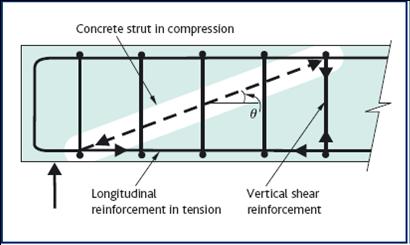
Eurocode 2 introduces the strut inclination method for shear capacity checks. In this method the shear is resisted by concrete struts acting in compression and shear reinforcement acting in tension. The angle of the concrete strut varies, depending on the shear force applied (see Figure below).
Figure 4: Variable strut inclination method
Extract from How to Design Concrete Structures using Eurocode 2 (page 34, Figure 4)
The angle of the concrete strut varies, depending on the intensity of the shear force applied (see Figure above). The lower the stress the lower the angle – subject to a minimum of 21.8º (when cot θ = 2.5), which most often proves to be the design variable strut angle.
The full procedure for determining the shear capacity of a beam section is shown below in Figure 5.
Figure 5: Procedure for determining vertical shear reinforcement
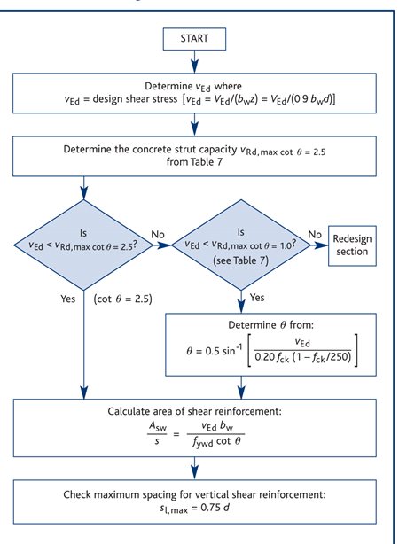
This is an extract from How to Design Concrete Structures Using Eurocode 2 (and includes UK NA values) and is in terms of shear stress in the vertical plane rather than a vertical force as given in Eurocode 2.
Most usually shear design will consist of comparing the design shear stress vEdd against allowable shear, vRd,c.
- If vEdd = VEd/bd < vRd,c (see Table 7A below), then in the case of one-way spanning slabs no shear reinforcement is required; in the case of beams nominal shear reinforcement is required. (NB For simplicity Figure 5 conservatively uses vEd in this regard.)
Then
- If vEd = VEd/zb = VEd/(0.9db) < vRd,cot q = 2.5 (Table 7 below), then the shear reinforcement may be calculated as:
Asw/s ≥ VEd/(978d) assuming fyw,k = 500 MPa and gsw = 1.15
- If vEd > vRd,cot q = 2.5 then checks against vRd,cot q = 1.0 (Table 7 below) and determination of q are required – see Figure 5 below.
- If vEd > vRd,cot q = 1.0 then a larger section or greater concrete strength is required.
vRd,c is dependent on amount of design tensile reinforcement and design concrete strength.
The maximum shear stress associated the minimum strut angle of θ =21.8º (when cot θ = 2.5) is relatively high (e.g. 3.64 MPa for a C30/37 concrete). So assuming θ = 21.8º and fywk = 500 MPa, As/sw usually ≥ VEd/(978d).
Where applied shear stresses are higher, one has to check against the maximum allowable shear stress at the maximum strut angle of θ = 45º (e.g. 5.28 MPa for a C30/37 concrete when cot θ = 1.0) and where necessary determine the actual intermediate strut angle, θ.
It is not usual for a slab to contain shear reinforcement. Therefore it is only necessary to ensure that the concrete shear stress capacity without shear reinforcement (vRd,c – see Table 7A below) is more than applied shear stress (vEdd = VEd /(bd )). Where shear reinforcement is required, e.g. for ribs in a ribbed slab, then the procedure is as for beams as outlined above and in Figure 5.
The UK National Annex limits the maximum permitted shear capacities to those of C50/60 concretes (5.52 MPa at cot θ = 2.5 and 8.0 MPa at cot θ = 1.0).
The triangulation of shear forces, should, in theory, increase the force in longitudinal flexural tension reinforcement. However, in practice, it is more convenient to extend the flexural reinforcement a distance al further than where it is required just for flexure. This ‘shift rule’ is discussed under Detailing.